|
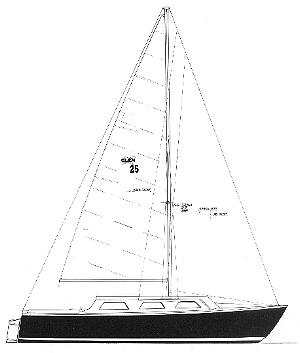
FIG. 2-1-A MASTHEAD RIG has the forestay attached to the top of the mast. This GLEN-L 25 has a backstay, upper shrouds, and two sets of lower shrouds supporting the mast. The boat uses a main and jib for working sails, plus an optional Genoa sail. |
Chapter 1
.....introduction
This book is a basic “how-to”
guide for rigging modern single masted sailboats up to about 25'
in length. Any person building his own small sailboat, buying a
new boat, or one who already owns a boat and wants to replace or
change the rig on his boat will find this book valuable. We have
attempted to write the book so it can be easily understood by
both the beginning sailor as well as the “old salts".
However, if you are looking for a “how-to-sail” book,
or a book on competition “tuning and racing,” or a book
on “sailing theory,” then this is not the book for you.
What is here is practical information on basic rigging and how to
install it.
Rigging means putting the spars and
related equipment in position so the boat is ready for sailing.
Rigging also means these items as a functional unit once
installed in the boat and made operational. Many terms used
herein may sound strange to the beginner and appear to have no
relation to the part they describe. Also, many of these terms
have no similarity or counterparts to terms used on shore.
Nevertheless, they are necessary to the business at hand.
Important terms that you should know are initially noted in BOLD
type and will be defined where they first appear, as well as in
the glossary. Don’t try to remember them all once, because
after you see them a few times, you’ll be able to relate the
term to the function, and soon it will become second nature.
The book is arranged in a logical
sequence. PART I concerns mainly the definition and function of
the various equipment used in rigging. PART II is the practical
“how-to” section on rigging sailboats. All
illustrations are noted by a “Figure number,” the first
number listed referring -lo the chapter. With the basic
information presented, we think you will be able to completely
outfit and rig your sailboat with ease and confidence. We have
purposely limited the scope of this book so as not to overwhelm
the beginner, and yet provide useful information to the large
majority of small boat sailors; those who sail the modern rigged
boats under 25' in length.
|
FIG. 2-1-A MASTHEAD RIG has the forestay attached to the top of the mast. This GLEN-L 25 has a backstay, upper shrouds, and two sets of lower shrouds supporting the mast. The boat uses a main and jib for working sails, plus an optional Genoa sail. |
Chapter 2
.....rigs and sails
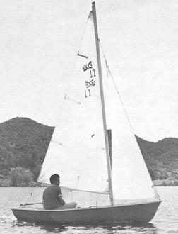 |
FIG. 2-2-A typical JIBHEAD RIG such as this GLEN-L 11 has the forestay attached to the mast at some point below the masthead. The mainsail on this boat, as well as those in FIGS. 2-3 and 2-4, is connected to the boom only at the clew and tack, making them “loose footed”; that is, not attached along the length of the boom. |
Everyone knows what a sailboat is and most people have heard expressions such as “sloop” or “ketch.” These words describe the configuration of the sails and masts on the boat, and we refer to this configuration as the RIG. Rigs have names which are defined by the number of masts the boat has; the number, shape, and locations of the sails; and sometimes by the position of the rigging on the boat. Most small sailboats under 25' have a single mast with one or two sails being used under normal sailing conditions.
RIGS
The
SLOOP rig has one sail forward of the mast, and one sail aft of
the mast. The stoop rig generally comes in one of two variations
depending on where the FORESTAY (the wire which supports the mast
from the forward side) joins to the mast. A MASTHEAD RIG, such as
shown in Fig. 2-1, has the forestay connected to the mast at the
very top of the mast (or MASTHEAD). A JIBHEAD RIG, as shown in
Fig. 2-2, has the forestay connected to the mast at a point
somewhat below the top of the mast. So, when we see a single
masted sailboat with a sail fore and aft of the mast and with a
forestay that goes to the top of the mast, we call it a
“masthead rigged sloop”; and when the forestay is below
the masthead, we call it a “jibhead rigged sloop".
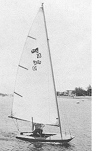 |
FIG. 2-3 -The typical CAT RIG uses a single mast well forward with the sail located on the aft side of the mast as shown by this GLEN-L 10. The stays consist of two shrouds and a forestay. |
A
boat with a single mast located well forward in the boat and only
one sail, which is aft of the mast, is called a CAT RIG (Fig.
2-3). Do not confuse this term with “catamaran,” which
is a twin hulled boat, but which may also have a “cat
rig.” Depending on the design, the mast of a cat rigged boat
may or may not be supported with wires (called “stays”;
see Chapter 4). Figure 2-4 shows a cat rig with a mast not
supported with wires, and is referred to as a
“freestanding” or “unstayed” mast.
Another
common rig used in small sailboats is the LATEEN RIG illustrated
in Fig. 2-5. This rig uses a single mast, somewhat short, and
usually unsupported with wires, onto which is attached two poles.
A triangular shaped sail is then attached to these two poles, but
not to the mast. The lower pole is sometimes not used, but the
rig is still called a “lateen.” The rigging of a lateen
is usually very simple and uncomplicated.
SAILS
Sails
can be considered the “engine” or power plant of the
sailboat, while the rigging can be considered the
“transmission,” or the means by which the power is
transferred to the boat to create motion. Therefore, to
understand the rigging, it is necessary to know something about
the sail configuration, because both work together as a unit.
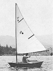 |
FIG. 2-4 -The GLEN-L EIGHT BALL dinghy uses a sock-type sail which slips over the mast. Because the mast is free-standing, no stays interfere with the sail along the mast. This boat is also called a “cat rig”. |
Just
about all small sailboat sails are triangular in shape, and the
terms used in describing one will generally apply to all. Modern
sails are most often made of synthetic fabric, usually polyester
(Dacron or equivalent). Some Nylon is used but it is considered
inferior because it stretches too much in use, except for special
sails such as spinnakers (see following). Sails in the past were
made from cotton fabric, and may be to this day, but these
require more maintenance and care. The sail of Dacron is
virtually maintenance-free; just keep them clean and dry, and
check occasionally for damage (see Chapter 11).
Sails
have names determined by their function and location on the boat.
On boats which have only one sail, this sail is always called the
MAINSAIL (the “main” sail on the boat). The lateen rig
sail, while still a mainsail, is commonly called a
“lateen” sail. Sloop rig sailboats have a mainsail
also, and this is the sail located on the aft side of the mast.
On sloop rigs, the sail forward of the mast is called the JIB,
and the main and jib sail when used in combination for normal
sailing are called the WORKING SAILS. The boat in Fig. 2-2 is
under sail with main and jib working sails.
Sails
other than working sails are sometimes used, especially when
racing or cruising. Two of the most popular types are the GENOA
jib and the SPINNAKER. The Genoa (commonly called
“jenny”) is actually just an oversize jib used to
increase the sail area, and hence the performance of the boat.
The boat in Fig. 2-1 is designed to use a Genoa jib. Sailboats
under about 16' long seldom use a Genoa. The spinnaker is a
parachute shaped sail (hence the nickname, “chute”)
used forward of the mast in place of the jib when sailing before
or with the wind. Because the spinnaker is considered a
“competition” item usually associated with larger
boats, and requires specialized gear, it is beyond the scope of
this book.
ANATOMY OF SAILS
The
common triangular sail is best discussed by referring to parts OF
the sail, and parts IN the sail, or the actual components used in
the construction of the sail. Our discussion of sail anatomy is
comprehensive, but note that not all sails will have all the
items mentioned. Fig. 2-6 should be followed in the discussion of
sail parts. Now for the parts OF a sail.
The
LUFF of the sail is the forward part, or the part which is
considered to meet the wind first. The LEECH is the aftermost
part, while the FOOT is the lower edge of the sail. The HEAD of
the sail is the topmost corner; the TACK is the forwardmost
corner, and the CLEW is the aft corner of the sail. The ROACH
refers to the up and outward curve in the leech of the sail. The
amount of roach will vary with the sail. The lateen-type sail has
little or no roach, while mainsails used on catamaran sailboats
have considerable roach. Next, we will describe the parts built
IN a sail.
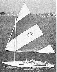 |
FIG. 2-5 -This GLEN-L BUCKBOARD uses a simple LATEEN RIG. The sail has a sewn-n sock along the luff at the clew to attach it to the tubular aluminum spars. No battens are used in the sail. This mast is also free-standing. |
To
the beginner, the most obvious part built into the sail is the
INSIGNIA and sometimes a group of numbers. The insignia usually
tells graphically what the name of the boat class is, while the
number refers to the registration number given to that particular
boat in the class organization. Obviously, not all sailboats
belong to a class, nor do they all have numbers on the sails.
Most
mainsails have BATTENS built into them. These are semi-rigid thin
strips, either of wood or synthetic material such as fiberglass
or plastic, used to maintain the shape of the sail when underway.
The battens fit into BATTEN POCKETS sewn into the sail. Battens
in order to stay in the pocket can be tied in. A better type uses
what is called a “lock-sleeve” pocket which makes it
impossible for the batten to slip out, but can readily be removed
so the sail can be folded. Battens are usually located at almost
right angles to the leech, but sometimes one or two battens are
located along the foot at right angles on LOOSE FOOTED mainsails
and some jibs. A loose footed sail is one that is attached only
at the tack and clew points along the foot. The boats in Figs.
2-2, 2-3, 2-4, and 2-5 all have loose footed mainsails. The
position and size of the battens is usually determined by the
sailmaker or the designer of the boat. Some sails, especially on
certain catamarans, use battens which span clear across the sail.
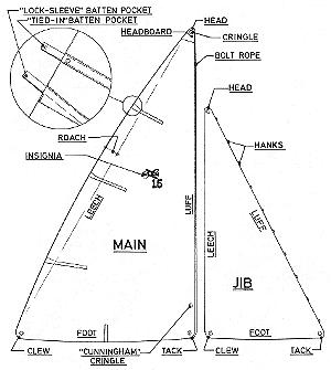 |
FIG. 2-6 -The “anatomy” of a typical set of working sails. The two dimensional drawing does not truly show the actual three dimensional shape which the sailmaker sews into the sail. This “shape” allows the sail to form correctly to the wind, even though the sail appears to be a flat piece of cloth. |
Other parts built into the sail
are primarily those used to attach the sail to the rigging. At
the head, tack, and clew, most sails have CRINGLES built in for
attaching the sails. These are merely grommets which reinforce
the sail at the hole. Most mainsails have extra sail reinforcing
at the head of the sail and this is called the HEADBOARD. The
strains on the sail at this point are great, and the headboard
with a cringle through it distributes the stresses.
Several
methods are used to attach the sails to the mast, boom, or
rigging. The jib and Genoa are attached to the forestay in sloop
rigs with HANKS or snaps (Figs. 2-7 and 2-8). These are special
hooks or rings used to secure the sails to the forestay as well
as allowing them to slide up and down. The hanks are usually sewn
into the luff of the sail. Probably the simplest method of
attaching the mainsail on lateen rigs, or in boats which have
free standing masts, is by means of a “sock” sewn right
into the sail which slips onto the spars. Two varieties of
sock-type sails are shown by Figs. 2-4 and 2-5. The sock-type
sail is limited to very small boats, but makes a neat and
inexpensive sail. Also used on small sails are loops or line
which fasten around the spars.
 FIG. 2-7 -Snap-type jib hanks sewn into the luff of the jib are used to attach the sail to the forestay. |
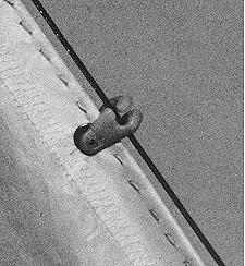 FIG. 2-8 -This type of jib hank takes just a twist of the wrist to secure it to the forestay. Larger jib sails usually do not use this type as they are not as strong as that shown in FIG. 2-7. |
On most boats, the mainsail is attached to the aft side of the mast in usually one of two ways. The first method is with TRACK SLIDES, pieces of hardware sewn to the luff of the sail at intervals of several inches, and which slide on a track fastened to the mast. A better and more common method is the use of a BOLT ROPE. This is a piece of rope the length of the luff and sewn right into it. The bolt rope fits into a groove built into the aft side of the mast. On sails which are not loose footed, this same bolt rope and groove can also be used for attaching the foot to the boom. Or, if track slides have been used on the luff, they too can be used on a track fixed to the boom. For details on spars (mast and boom), see the next chapter.
Chapter 3
.....masts and booms
 |
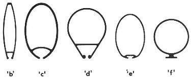 |
| FIG. 3-1-Some typical aluminum mast sections. Sections 'a', 'b', 'c', and 'd' have built-in grooves for the bolt rope of the sail. Sections 'e' and 'f' are made for sails with track slides, with 'e' using and internal slide and 'f' using an external slide. All these sections are made by extruding the metal. Ordinary aluminum tubing is also used for spars in some cases, where the strength is sufficient. Most of these sections could be used for the boom also, if of the appropriate size and shape. | |
Most people
know a SPAR when they see one, and in sailing, the spars are the
“sticks” (mast and boom) to which the sails are
attached. To BEND the sails means to attach the sails to the
spars and rigging. The MAST is the more-or-less vertical member,
while the BOOM is the more-or-less horizontal member attached in
some manner to the mast, and usually capable of pivoting about
the mast. Most sailboats of the type discussed in this book have
one of each. One exception is the lateen rig, which often has two
booms, with the upper boom correctly referred to as the
“yard” (see Fig. 2-5).
Spars on sailboats are usually made
either of wood (solid or hollow), or aluminum (extrusions or
tubing, both hollow). It is not uncommon nor undesirable to have
an aluminum mast and wood boom in combination. Some typical
sections through masts and booms are shown in Figs. 3-1 and 3-2,
both for wood and aluminum. Masts made from aluminum should be
“anodized”; a special coating process which minimizes
oxidization. It is also desirable to wax aluminum masts.
Observe the methods used for sail
attachment. The groove-type mast in either wood or aluminum makes
the neatest installation besides being the most efficient. Wood
booms are usually solid in the size boats being discussed in this
book, due to the small relative size required for the boom. On
small sails such as used on lateen rigs, the spars are often
nothing more than round wood poles or aluminum tubing.
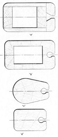 |
FIG. 3-2-Some typical wood mast and
boom sections. Section ‘a’ is a mast made from
plywood which can be relatively easy to build by the
amateur. Section ‘b’is made in two halves glued
at the centerline. Because sections ‘a’and
‘b’are hollow, the halyards can be run
internally. Blocking for reinforcement is provided in the
hollow area, where fittings are located. Section
‘c’ is a solid wood shaped mast built in two
halves about the centerline in a similar manner. Section
‘d’ is of single piece wood construction.
Sections ‘a‘ ‘b ‘c, and ‘d’
have built-in bolt rope grooves. That of section
‘a’ is easily cut on a saw set to the proper
angle. The groove of sections ‘b’and
‘c’can be cut before the two parts are
assembled by running the spar angularly over a circular
saw with the blade raised to the proper depth.
Optionally, the groove can be cut with a core box bit and
router. The groove in section ‘d’ must be cut
with the core box bit because of the one-piece
construction. Any of these sections could also be used
for the boom if there is a bolt rope in the sail along
the foot, and the boom was properly sized. Boom section
‘e’ is a typical “T” configuration
which could also be inverted. A track is shown for use
with a sail with slides on the foot. Section
‘f’is a rectangular boom used with loose-footed
sails. If stiffness was required, the “T”
configuration could be added, or a square piece added to
each side making a cross-type section. Some degree of
flexibility, however, in the boom is desirable.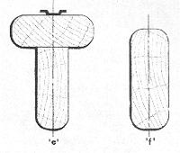 |
|
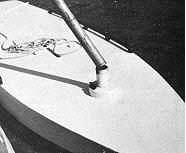
FIG. 3-3 The mast step is any receptacle that maintains the position of the mast in the boat. This sailboard has a mast which consists of a piece of ordinary pipe used to receive the tubular aluminum mast. |
| The base of the mast always fits into
some type of receptacle or apparatus which is called the
MAST STEP. Many types of mast steps are used depending on
the configuration desired. Putting the mast in position
on the mast step is called STEPPING the mast (see Fig. 9-1). Some masts go
through holes in the deck or cabin top and step onto the
hull structure, while others bear directly on the deck or
cabin top. The simplest type of mast step is the fixed
type such as shown by Figs. 3-3 and 3-4. The mast is
fixed in position on the step and no movement of the mast
is possible, short of removing the mast. Most masts
stepped through the deck use fixed steps. Another type is
the rotating mast step shown in Fig. 3-5. This type
allows the mast to turn or rotate with the direction of
the mainsail for greater sail efficiency. A convenient type of mast step, as far as ease of stepping the mast is concerned, is the pivoting type such as shown in Fig. 3-6. This type allows the mast to be laid into the step fitting, bolted, and pivoted up in position, as opposed to trying to lift it onto the step, which can be tricky, especially on a windy day or if it is a tall mast. With lightweight aluminum spars, it is desirable to use a mast base stiffener at the step when using the pivoting step in order to provide adequate bearing for the pivot bolt. Many masts require extra reinforcement, and one method of doing this is by utilizing SPREADERS. These are cross members located on the mast at a predetermined location and jutting out sideways. Spreaders are always arranged in pairs, one on each side of the mast. The spreaders “push out” or spread the SHROUDS (the wires supporting the mast from the sides; see Chapter 4) to help stiffen the mast. While spreaders can be made of wood, it is common on small sailboats to have them made of metal tubing, usually stainless steel or aluminum, even when wood masts are used. Some boats do not have any spreaders, while others may have one, two, or more sets. Since spreaders are a necessary evil, (they get in the way and foul things aloft, not to mention added resistance and weight), it is best to have as few as possible. |
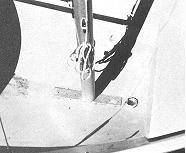 FIG. 3-4 This GLEN-L 11 has an adjustable mast step arrangement that allows the boat to be sailed as a cat rig when the mast is moved forward onto the fixed step (to the right), or as a sloop rig when the mast is moved aft along the metal bar base.
|
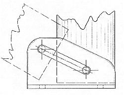 |
FIG. 3-6 A pivoting mast step can be made using aluminum or steel plate or channel. The base has two upright plates welded or formed into a "U" shape, spaced to match the width of the mast. A slot in each |  |
| Two types of spreaders are used. One is
the fixed-type where the spreader is rigidly mounted to
the mast such as shown in Fig. 3-7. The other type is the
pivoting or swinging type which is allowed to swing
horizontally along a pivot point located on the mast.
This type is illustrated in Fig. 3-8. Use the type
specified for the boat you have in any case. Where the
shrouds pass over or through the spreaders, there should
be special fittings or spreader tips which prevent
chafing of the shroud by the spreader. Often the spreader
tips are adjustable in order to vary the tension of the
shrouds. Most spreader tips have an open groove or hole
through which the spreader passes. Note that the shrouds
are allowed to move or slide on their own against the
spreader tip. However, with the open groove type, some
means of lashing or taping the shroud to the spreader tip
must be provided. The reason for this is that when
sailing at an angle of heel, the WINDWARD* shroud will be
taut, and the LEEWARD* shroud becomes slack, which could
allow the shroud to fall out of the leeward groove if not
secured in place. *WINDWARD - Toward the direction from which the
wind is blowing. Two other types of spreaders which are
used for supplemental strengthening of the mast, or to
combat localized stresses, are DIAMOND SPREADERS and
JUMPER STRUTS (see Fig.
4-4’a’). Diamond spreaders are cross
members in pairs always used in conjunction with DIAMOND
STAYS, which are wire rope stays fixed at either end to
the mast. The diamond spreader "spreads out”
the diamond stays at their mid-length each side of the
mast. The term diamond comes from the fact that when the
diamond stays and spreaders are in position, they form a
shape like a diamond. An exception to this is when more
than one diamond spreader pair is used per stay. Diamond
spreaders are just like regular spreaders, except that
they are usually smaller and shorter in length. |
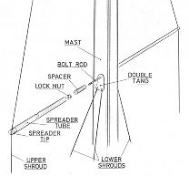 FIG. 3-7 An example of fixed spreaders. This spreader fitting consists of a bolt or threaded rod through the mast, with a spacer on either side, that matches the inside diameter of the spreader tubing. The spreaders are aluminum tubing with sloted tips for the shrouds. This fitting can be used on either wood or aluminum masts.
|
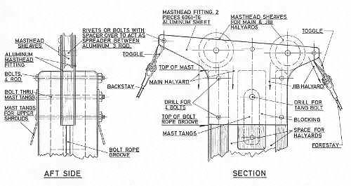 FIG. 3-9 Masthead fitting for a wood mast on a masthead rig. This fitting can be easily made by the home builder. Aluminum plate is used to keep weight to a minimum, which is critical to stability when located aloft. The toggles allow a universal swivel action to the stays, thereby eliminating bending of the stay at the swaged fitting. Note that the halyards are running inside the mast. |
|
| The top of the mast is called the
MASTHEAD, and depending on the type of rig, the fittings
located here will perform various functions. Masthead
fittings will also vary depending on whether a wood or
aluminum mast is being used. The masthead fitting for
wood masts is usually a custom unit made by the builder
(see Fig. 3-9). When building a boat using wood spars, it
is usually necessary to fabricate a masthead fitting. The
designer should provide details for making the masthead
fitting. For aluminum masts, the masthead fitting is
usually a ready-made unit or “kit”-type
assembly to match the mast extrusion, such as illustrated
in Figs. 8-4 and 8-5.
Obviously a masthead fitting for a masthead rig will be
more complex than for a cat or jibhead rig. In any case,
the masthead fitting contains at least one SHEAVE (a
grooved wheel or pulley) for the main HALYARD, the line
used to hoist the sail. With masthead rigs, the masthead
fitting has a sheave for the jib halyard as well, and
usually incorporates attachment fittings for the stays,
and sometimes for the shrouds also. When a sock-type sail
is used, and when the mast has no stays, then no masthead
fittings are required. In any case, the top of hollow
spars should be capped to keep water out. On wood spars
this can be a sheet metal cap, and with aluminum spars,
the masthead fitting will usually do the job. On boats where the stays and shrouds do not go to the masthead, but fasten to the mast at some lower point as in jibhead rigs, other means are used to secure stays and shrouds to the mast. With wood spars, the conventional method used to attach the shroud and forestay is to use TANGS. Tangs are short metal straps usually with a crimp or bend to splay them out from the mast when in position. Another type does the same job, but these are of cast metal. The strap type usually has at least two holes; one for the stay attachment, and the other for fastening the tang to the mast. When aluminum masts are used, tangs bolted together through the mast can also be used for the shrouds, but the forestay usually uses another fitting called a HOUND (see Figs. 3-10 and 3-11). The hound wraps around the mast for bearing and has a fitting to receive the forestay. If used on a boat with a jib, then a JIB HALYARD BLOCK (fitting with a sheave used to lead the halyard and change its direction) is attached to the hound. If the shrouds and forestay land at the same point on the mast, then the tangs for the shrouds can be integral with the hound fitting. |
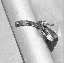 FIG. 3-10 & 3-11 A hound strap fitting for use on jibhead rigs with aluminum spars. The hound provides attachment for the forestay as well as a block for the external jib halyard. The main halyard can be run either internally or externally. If run externally, it would run down the forward side of the mast along with the jib halyard (the most common arrangement on small boats).
|
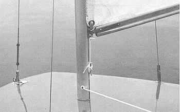 FIG. 3-12 This
photo shows several things. First note the relieved area
along the mast for the sail bolt rope and gooseneck. The
gooseneck has a shackle fitting with a pin through the
cringle at the tack of the sail. The downhaul is used to
tension the luff of the sail, and the line secures to a
jam cleat on the mast. While the mast is aluminum, the
boom is made from wood and is in an upsidedown
“T” configuration for added strength. A
fairlead at the mast base is used for the exit of the
internal halyard which runs aft to a jam cleat on the
deck. This small sailboat uses a stay adjuster on each
shroud with tension adjusted by use of a turnbuckle on
the forestay. The shrouds connect to chainplates, while
the forestay fastens to a stemhead fitting. FIG. 3-12 This
photo shows several things. First note the relieved area
along the mast for the sail bolt rope and gooseneck. The
gooseneck has a shackle fitting with a pin through the
cringle at the tack of the sail. The downhaul is used to
tension the luff of the sail, and the line secures to a
jam cleat on the mast. While the mast is aluminum, the
boom is made from wood and is in an upsidedown
“T” configuration for added strength. A
fairlead at the mast base is used for the exit of the
internal halyard which runs aft to a jam cleat on the
deck. This small sailboat uses a stay adjuster on each
shroud with tension adjusted by use of a turnbuckle on
the forestay. The shrouds connect to chainplates, while
the forestay fastens to a stemhead fitting. |
|
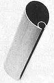
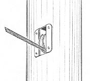 FIG. 3-13 The sheave box is built into the mast at the exit point of the internal halyards to reduce chafe on the halyard. |
When using internal halyards (those which run inside the mast), some type of fitting must be provided for the mast where the halyards exit the mast. Internal halyards can only be used in a hollow mast, and where used, they usually exit at or near the mast base. The simplest fitting is merely a hole through the mast fitted with a FAIRLEAD (a fitting to give a line a “fair lead”) to prevent chafing the line (see Fig. 3-12). Another arrangement is to use COAMING PULLEYS or SHEAVE BOXES which not only act as a fairlead, but have sheaves incorporated to change direction of the halyards as well as preventing chafing of the line (see Fig. 3-13). These fittings are usually fitted into the mast near the base. In selecting coaming pulleys and sheave boxes, be sure the sheave of the fitting will protrude far enough into the mast so the halyards will not chafe along the inside mast surface. |
| The GOOSENECK is the fitting used to
connect the boom to the mast and allow it to move freely,
like a universal joint. On the small lateen rig boats the
gooseneck is two connected loops which rotate
independently (see Fig. 3-14). On conventional rigs, a
basic gooseneck is the fixed base type which fastens to
the mast. For better sail adjustment, the type of
gooseneck which slides on a track or in the mast groove
is superior (see Fig. 3-15). Whichever of these types is
used, they can be bought as non-swiveling or as a ROLLER
REEFING type. The non-swiveling type as shown in Fig.
3-15, does not permit the boom to rotate. The roller
reefing type shown in Fig. 3-16, is used so the boom can
rotate and allow the sail to be rolled onto the boom in
order to reduce sail area when sailing in heavy winds.
Goosenecks come in many styles both for wood and aluminum
booms with or without the roller reefing feature. The CLEW OUTHAUL at the other end of the boom is similar in function to the masthead fitting. It is used to attach the clew of the sail to the boom. Where the mainsail is small, the clew outhaul is sometimes nothing more than a line tied to a cleat. Another method is to use a sheave in the end of the boom in order to gain some leverage so the sail can be pulled taut (see Fig. 3-17). With larger mainsails, the clew outhaul is best a slide fitting located on a length of track, or a type which fits into the boom groove if there is one (see Fig. 3-18). On aluminum booms, and especially when roller reefing is used, a boom outhaul fitting is used which performs the clew outhaul function as well as providing a tang for attaching the hardware used to control the sail . Other incidental fittings may often be attached to the spars as well. CLEATS (a fitting used to belay or secure a line, Fig. 3-19) or BOOM BAILS (“U”-shaped straps used to attach blocks to the boom, Fig. 6-2) are commonly used. A BOOM CRUTCH is another item sometimes used, which is not really a part of the boom. The boom crutch holds up the boom when the sails are furled and when hoisting the sail, in order to keep the boom in its proper position. |
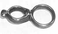 FIG. 3-14 This is a gooseneck used on boats with lateen rigs such as shown in Fig. 2-5. The small loop is secured to the boom while the mast fits loosely into the big loop so that the gooseneck can move freely along the mast.
|
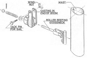 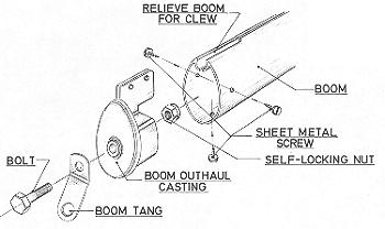 |
FIG. 3-16-Exploded view of a roller reefing boom assembly. The boom can be pulled aft on the gooseneck and rotated by hand to roll the sail onto the boom. When released, the boom then returns to its position on the gooseneck because of the pressure set up by the spring. The mainsheet fittings are secured to the tang at the aft end of the boom which is secured with the bolt slightly loose so the boom will rotate, while the tang remains stationary. |
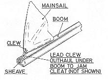 FIG. 3-17-A clew outhaul on a loose-footed sail The boom is slotted at the aft end for a sheave which allows the line to be lead to the underside of the boom where it can be cleated. A simpler type used on very small boats consists of merely a slot or groove in the end of the boom in place of the sheave. |
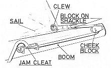 FIG. 3-18-A more sophisticated clew outhaul arrangement uses a line dead-ending on the opposite side of the boom (not visible) and running through a block shackled to the clew of the sail. The line then passes through-a cheek block on the side of the boom and to a jam cleat where it can be belayed. The sail can be secured to the boom with either a bolt rope groove or slides on a track. This arrangement has a built-in power advantage thereby allowing greater tension to be placed along the foot of the sail. |
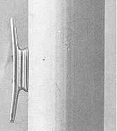 FIG. 3-19-A CLEAT is a fitting to which a rope
may be belayed. This metal cleat is fastened to the side of a
mast to belay a halyard, and is a typical example of a cleat.
FIG. 3-19-A CLEAT is a fitting to which a rope
may be belayed. This metal cleat is fastened to the side of a
mast to belay a halyard, and is a typical example of a cleat.
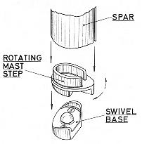
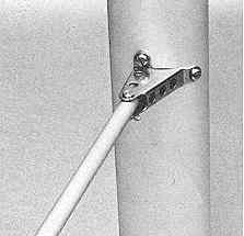
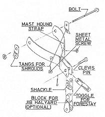
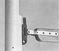 FIG. 3-15-A typical gooseneck
showing the tack shackle, downhaul eye, and tangs which
lap each side of the boom. Note the relieved area for
feeding the sail bolt rope and installing the gooseneck
to the mast.
FIG. 3-15-A typical gooseneck
showing the tack shackle, downhaul eye, and tangs which
lap each side of the boom. Note the relieved area for
feeding the sail bolt rope and installing the gooseneck
to the mast.